


Today we all are much concerned about the non-renewable energy conservation issue. Solar powered equipment are always on demand as they need only one time cost for installation and you can use it for the rest of the life without causing any harm to environment. Here is one such solar product that you can make on your own. Yes, now you won’t need to use electricity to cook food in the electric oven, just some sunlight and your food is ready. This solar oven will make your work simpler. Usual solar cooking take a whole day, but this is a different solar oven that has a rotating platform, which can be controlled with the help of an Arduino microcontroller. This oven will follow the sun until the food is cooked and later on it turns the oven away from the sun.
Difficulty level: Moderately challenging. It may require expertise in some areas
Time required: 2-3 days
Resources required:
1. Tools
2. Wooden box that is large enough to accommodate an 18″ circle on the top.
3. 12 inch Lazy Susan Bearing
4. Steel bolt
5. 1 inch long 4 sheet metal screws
6. 1/4-20 bolts and nuts and ¼ inch washers
7. 18 inch diameter round plywood
8. 1/2-3/4 inch long 4 wood screws
9. 1 inch fender washer
10. 3/4inch long piece of 1 inch PVC pipe
11. 1 1/2″ wood screw
12. Motor and gear head from a cordless drill
13. 7inch x 3inch piece of ¾ inch thick plywood
14. 1 1/4 inch diameter small rubber caster
15. 4-inch length of 1/4-20 threaded rod
16. 2 1/4-inch nuts washers
17. Small eye screw
18. 4 pieces of aluminum sheet metal
19. 4-5 feet length of 2-conductor wire capable
20. 1 Microswitch with lever arm
21. 2 small wood screws
22. 1 small, thin piece of wood ~1 x 2 inches
23. 2 phototransistors
24. 6-32 screws (1/2-3/4 inches long) and nuts and washers
25. Epoxy
26. 3-conductor wire
27. Stereo phone plug
28. 1 temperature sensor
29. 1 Arduino microprocessor
30. 1 breadboard
31. Transistors
32. 1 rectifier diode
33. Resistors
34. 8 LEDs
35. 1 2 x 3 inch IC circuit board
36. Right angle male and female connector
Instructions
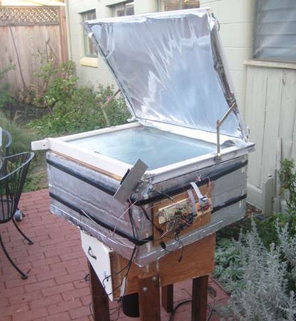
Step 1: The box cooker
The oven is a usual box cooker with some typical materials. The box is prepared from firm polyurethane insulation.
Step 2: The rotating platform
The solar oven is placed on a wooden circle with 18 “diameter that is fixed firmly with screws to a Lazy Susan bearing of 12″. This bearing is secured to the top of a five-sided wooden box. You can also make use of a kitchen cabinet which is no more of any use as the box. Add legs to the base of the box which will enable the oven to sit at a height. As an easy option you can also place it over a table.
Step 3. Motor drive assembly
The gear motor used in this oven is taken from an old or useless cordless drill. The motor has a planetary gearhead which is an ideal option for the application. You can substitute this gear motor with any DC motor/gear combination. The entire motor assembly is slightly long so you need the platform box to be tall enough to accommodate it. In case if you are making use of a traditional gearhead you can use a smaller platform box. Fasten a small wheel on the top of gearhead with some O-rings made of rubber.
Steps to mount the drive motor:
1. The main part of this mechanism is a clamp which is made of 3/4 inch plywood. Firstly sketch the shape of the part in pencil.
2. Cut the motor clamping circle using a hole saw also draw the outlining cuts using a hand saw.
3. Drill the holes with a drilling machine for the clamp screw.
4. Also drill holes for the pivot.
5. Make a U-bracket that will tie up the assembly to the aluminum sheet metal box.
6. Use the small eye screw to fasten in to the end of the clamp, at the distance same from the motor axis as the distance from the pivot and the contact point of the drive wheel. Ensure that when you hang some weight from this eye screw, it should work as a lever.
7. Bring together the motor in the clamp collectively with pivot and the U-bracket.
8. Now put in the drive wheel all the way through the opening in the box.
9. From beneath, cautiously place the U-bracket in the accurate position and mark the positions of the through holes on the box.
10. Now drill the two U-bracket holes on the box and fix the U-bracket to the box using nuts and screws.
Step 4: Sun sensor
The sun sensor makes use of two phototransistors that is separated with the help of a small partition. When the sun lights one phototransistor and the other one gets shadowed because of the partition. The platform rotates till both the transistors get lightened up by the sun. Following are the steps to make sun sensor:
1. Drill 2 holes in piece 1, which is equal to phototransistors’ size 1/2 inch away from each other.
2. Make a bend at 90 degree in piece 1.
3. Bend piece 2 such that the partition is about 2 inches tall.
4. Place the partition in a way as such that it is accurately in the middle of the two holes in piece 1 and mark the position of the hole onto piece 2. Now drill out a hole in piece 2 at this position.
5. Now attach both the piece 1 and 2 jointly using a tape, place the partition in the proper place and drill screw holes through these pieces.
6. Firstly, you need to identify the collector as well as the emitter of both the transistors and make some marking on them to identify it properly.
7. Now glue both the phototransistors into piece 1 among epoxy.
8. Let this to dry. After that solder the leads in to the 3-conductor wire.
Step 5: Temperature sensor
For a temperature sensor, make use of either an LM135 or LM335 as both of them are integrated circuits that have three leads. You can also substitute it with a thermistor or some other compatible temperature sensor. The best solution is to look out for wires that have insulation rated for high temperatures.
The temperature sensor must be water proof to make it easy enough to insert in the food that is to be cooked as well as it need to be food safe. For this purpose, wrap it in aluminum foil while you are using it for cooking.
Step 6: Electrical diagram and schematic
You need to pen down the diagram for the circuit before you start with it. This diagram will help you know how to make it and will let you know if you go wrong anywhere.
Step 7: Testing
After installing the program, now it’s time to test your oven. Place the oven in a place in your garden such that it receives ample sunlight during the day. Track the food temperature and the cooking temperature.
If the temperature of food is less than cooking temperature, it means the oven is in pre-heating mode it will track the sun.
If food temperature is greater or equal to the cooking temperature, it refers that the oven is in cooking mode. It will track the sun and at the same time bring down the cooking time.
When the cooking timer reaches zero, the oven will start to rotate continuously.
Frequently asked questions
Q. I don’t have a box solar oven? Can I follow these steps if I am using any other type of solar oven?
A. These instructions are for box cooker. If you are making use of some other type of solar oven, you will need to make a few modifications.
Quick tips
1. If you are a person living in the tropics, the sun light may not be high. So, there is no point in completely turning the oven away to stop cooking. In such case, the best solution would be to make a mechanism that will close the reflector above the top of the cooker.
2. Make the motor solar powered by making use of a small solar panel to charge a battery.
Things to watch out for
The LM135 or LM335 have three leads. But, you will have to use only 2 leads. The third one is for precisely calibrating the sensor, if required.